Monday, February 24, 2014

How to block facebook in Mikrotik using L7 Protocols (Layer 7)

How to block facebook in Mikrotik using L7 Protocols (Layer 7)

In Some Scenarios , We May need to Block Facebook Social Website or some others …In this tutorial, I will show you, how to achieve this goal using L7 (Layer7).

This tutorial consists of two parts:
1- Block facebook website for everyone on local network.
2- Allow facebook for specific host(s) and block for others on local network.
1- Block facebook website for everyone on local network.
First we check that Facebook is currently working on our local network or not?

Check the IP address of our client?

We need to create new Regexp rule at Layer7 Protocols, in order to block the facebook for our local network.
To achieve this goal, please follow these steps:


^.+(facebook.com).*$

Now, we need to create Filter Rule, using these steps:


Now test the rule, that we just created:

Try also on 2nd client (172.16.10.199/24):


Check that it only block facebook or other websites also?

Oh yes, our rule is working perfectly :)
2- Allow facebook for specific host(s) and block for others on local network.
Now, we want to allow facebook for 2nd client (172.16.10.199/24) but still want to block it for other host(s).

To accomplish this goal, we need to create a second Filter rule, to do this, please follow these steps:


Move this rule at the top:

Test this rule on 2nd client (172.16.10.199/24):

Verify the rule on Mikrotik:

Verify that, facebook is still blocked for other host(s) on the local network:

Verify the rule(s) on Mikrotik:

Drop packets rate are incremented!
We can do the same for youtube or any other website!
Hope this will help you!
Please Remember me in your prayers!
Enjoy :)

Saturday, February 22, 2014

How to put online your WampServer

How to put online your WampServer

WampServer LogoOn your Windows machine you run an Apache web server with some PHP websites in there. What if you want to show all of them to your friends, or want to be reachable by the whole Internet? This may sound quite difficult to achieve, but actually it’s fairly straightforward to put online a web server: let’s see how.

Publishing your Website on the Internet

First of all, you need to get your WAMP stack up and running on your local host. I’ll assume you already have a web application hosted on your own PC, and that is reachable by just typing this URL in the address bar:
http://localhost/    # or http://127.0.0.1
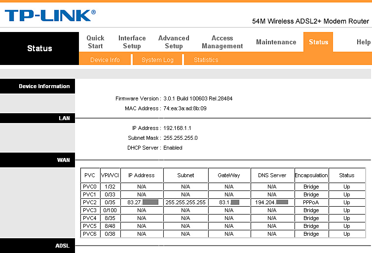
Now you should access to your router web interface. Usually it is reachable by navigating to:
http://192.168.1.1
However this may vary, depending on your router model. When in doubt, open the command prompt (cmd), type ipconfig and press enter. You should see something like this:
C:\>ipconfig
Ethernet adapter Local Area Connection:

    Connection-specific DNS Suffix  . :
    IP Address. . . . . . . . . . . . : 192.168.1.27
    Subnet Mask . . . . . . . . . . . : 255.255.255.0
    Default Gateway . . . . . . . . . : 192.168.1.1
Please take note of the IP address: that’s your private address, which uniquely identifies you in your local network. If you try it in your browser, you should be able to see the public contents of your server.
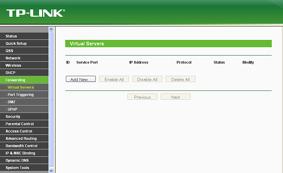
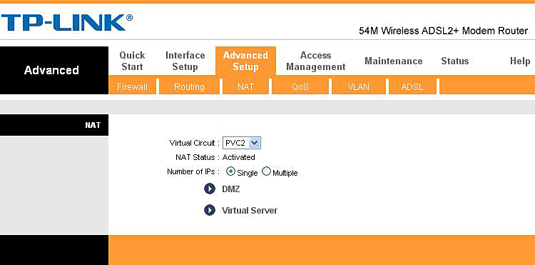
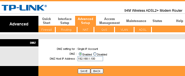
Port Forwarding

In order to be reached by the world, you should tell your gateway where is your web server. All incoming request on port 80 should be redirected to your own private IP address. Even this process may vary; it really depends on your router. By the way, this is what you basically want to do: forward every request on port 80 to 192.168.1.27 (of course you must use your own IP address). But since the router’s web server already keeps the port 80 busy, here’s what you can do:
  • Move the gateway’s web interface to another port;
  • Move your web server to another port.
I’ll pick the last one, since it’s usually easier to do, and the first option is not always possible. So, let’s change the port: open the httpd.conf and find this row:
Listen 80
replace it with:
Listen <port number>
for example:
Listen 8080
And restart the server. Now go to http://localhost:8080 and check that everything went as expected.

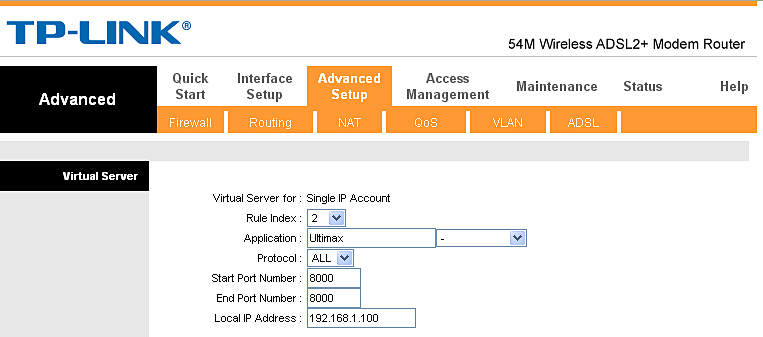
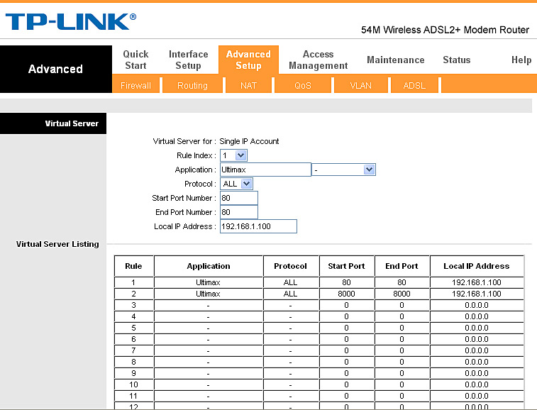
Routing the outside web traffic to your own web server

All respectable routers have an advanced section called IP/Port Forwarding: find yours. If you don’t have this, I’m afraid you cannot be reachable by the outside.
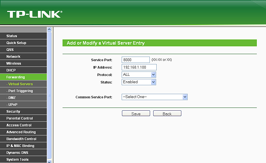
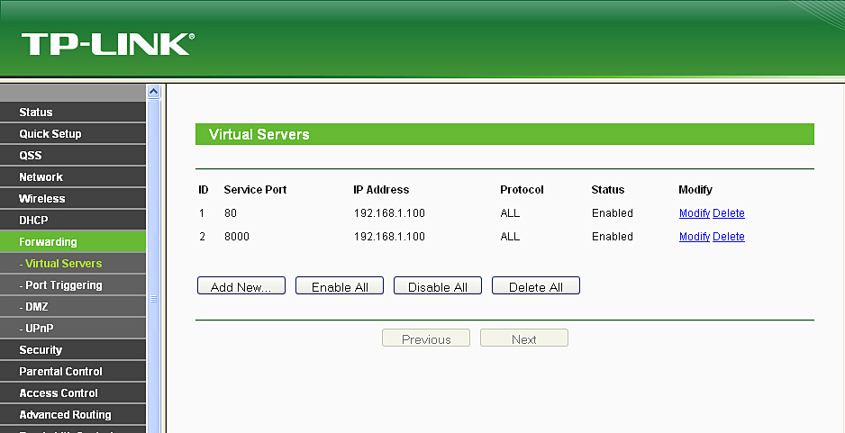
Usually you need to add two separate entries: one for TCP and one for UDP packets. Something like this will do the work:
Private IP     Private Port   Type   Public IP/mask   Public Port
192.168.1.27   8081           TCP    0.0.0.0/0        8081
192.168.1.27   8081           UDP    0.0.0.0/0        8081
Apply the changes and restart your router.

Configuring the server to be reachable by everyone

The last step! Open your httpd.conf and find this line:
ServerName localhost:80
Change it to:
ServerName <your private IP>:80
Example:
ServerName 192.168.1.27:80
Just a quick note: you can jump over the step below. It can be done in an easier way by just clicking on the green WampServer tray icon and choosing “Put Online”.
Also find this line:
Order Deny,Allow
Deny from allAllow from 127.0.0.1
Change it to:
Order Allow,Deny
Allow from all
Restart your web server. Now just find out what’s your current public IP address and try to go to:
http://<public IP address>:<port>/
i.e.:
http://13.37.223.21:8080/

Wednesday, February 19, 2014

How To Block Facebook with Mikrotik


How To Block Facebook with Mikrotik

From time to time, some employees doesn’t understand the normal language and the only thing you can do is to use force. Facebook is good and nice thing but only if you’re a reasonable person which understand the terms like “working hour”, “job to do”, etc…
Here are the few tricks which can help you to totally block Facebook.
Create two lists (fb for Facebook IPs and fbWhitelist for local computers which you want to exclude from restrictions)
/ip firewall address-list
add address=192.168.1.195 comment="" disabled=no list=fbWhitelist
add address=192.168.1.198 comment="" disabled=no list=fbWhitelist
add address=192.168.1.194 comment="" disabled=no list=fbWhitelist
add address=31.13.24.0/21 comment="" disabled=no list=fb
add address=31.13.64.0/18 comment="" disabled=no list=fb
add address=66.220.144.0/20 comment="" disabled=no list=fb
add address=69.63.176.0/20 comment="" disabled=no list=fb
add address=69.171.224.0/19 comment="" disabled=no list=fb
add address=74.119.76.0/22 comment="" disabled=no list=fb
add address=103.4.96.0/22 comment="" disabled=no list=fb
add address=173.252.64.0/18 comment="" disabled=no list=fb
add address=204.15.20.0/22 comment="" disabled=no list=fb
Add filter rule with

/ip firewall filter
add action=drop chain=forward comment="facebook drop" disabled=no 
dst-address-list=fb dst-port=80 in-interface=lan protocol=tcp 
src-address-list=!fbWhitelist
 
That’s it.
Now if you want to exclude some IPs, just add them to fbWhitelist and they won’t be blocked.

Mikrotik : How to Block Facebook - Youtube and Other sites using L7 (Layer7)

Mikrotik : How to Block Facebook - Youtube and Other sites using L7 (Layer7)

Below i will show you how to block facebook and youtube sites using Mikrotik L7 Protocols (Layer 7). here i use RouterBoardOS RB1100.

STEP 1:
you have to create new Regexp rule at Layer7 Protocols by Press , and name it as "DENIED" (withoue quote), see details below:

You can Copy & Paste the code above at below:
^.+(facebook.com|youtube).*$

STEP 2:
Now create Filter Rules, as follow:
At General Tabs for Chain, Please Choose : Foward

At Advanced tabs, select 'DENIED' (rule that you have create at step 1) for Layer7 Protocols

Choose Action 'DROP' 
And At last, your Filter rule to block facebook and youtube should have effected to your network.
try to access facebook & youtube, and you will see that the two sites will not able to access.

this can be see from the filter rule you have created, it will catch the bytes for denied sites in your network.

Mikrotik: Blocking Unleased DHCP IP Address

Mikrotik: Blocking Unleased DHCP IP Address

The case this time is how we block users other than DHCP Client with Mikrotik Winbox, in the other word that users who use a static Ip Address instead of DHCP.

ip can not use our connections. Just who gets an IP address via DHCP Server mikrotik who can use the internet connection,

I asume that Your DHCP server in mikrotik router are already running well.
We only need to change some the existing settings. 
  1. Sign In to Your Mikrotik Via Winbox
  2. IP menu> DHCP Server click 2x on the DHCP server. And Check "Add ARP For Lease"
  3. Go to menu "Interfaces" click 2x on your local interface or an interface where you apply a DHCP Server And Replace option "ARP" to "reply-only '
DONE! Now you try to use a static IP on your computer at yourlocal network, connections to the router will not work unless you use the options "Obtain an IP Address Automaticaly" or DHCP on interfaces / ethernet your computer enabled.

Tuesday, February 18, 2014

Utilizing Port Forwarding on Mikrotik Router

Utilizing Port Forwarding on Mikrotik Router

Port Forwarding is a feature on the proxy to forward specific IP with port specified, all other IP port specified as well. Generally used to direct public ip to the client ip (local ip). There are so many benefits of this feature, of which we can access the webserver on the local network even if we are not in a local network. This can also be done not only on service webserver only, but it can also be applied to other service2, such as File Server, Mail Server, SSH Server, VNC Server, and more.

assumptions:
Using WinBox
Public IP from your ISP: 180 241 111 312
Local IP:
- Webserver IP: 192.168.1.10
- Fileserver IP: 192.168.1.20
- SSH Server IP: 192.168.1.30
Forward IP to Web Server
Because web servers generally listen on port 80, so in this case we forward port 80.
Stepnya as follows:
Open New Terminal in Winbox, then type the following command:
/ip firewall nat add chain=dstnat dst-address=180.241.111.312 protocol=tcp dst-port=80 action=dst-nat to-addresses=192.168.1.10 to-ports=80 comment=”forward web server”
Forward IP for File Server
Such as SAMBA fileserver or else generally listen on port 139. Well .. we are here to change the port to 139.
Open New Terminal of Winbox, then type the following command:
/ip firewall nat add chain=dstnat dst-address=180.241.111.312 protocol=tcp dst-port=139 action=dst-nat to-addresses=192.168.1.20 to-ports=139 comment=”forward file server
for other services can be done in the example above .. just by our changing the direction where the ip in forward and change the port.
Note:
We should not dst-port according to the port listen on its service each. For example, we want to make ip_public: 3000 forwarded to the SSH server (port 22), we can make the following:
/ip firewall nat add chain=dstnat dst-address=180.241.111.312 protocol=tcp dst-port=3000 action=dst-nat to-addresses=192.168.1.30 to-ports=22 comment=”forward SSH server”
It is important to keep the default port is not compromised. so in this case when we want to SSH to Mikrotik Router .. us enough access to the SSH client public ip, it will go directly to the SSH server on the proxy, but if we access the public ip to port 3000 via SSH client, it will be forwarded to the SSH server on the local computer to 192.168.1.30
By : teknosia

Step by Step build a VPN Server with RouterOS

Step by Step build a VPN Server with RouterOS

VPN is a VPN Virtual Private Network which is an interconnected network (PC Client to LAN or LAN to LAN) which interconnect with the Public network (Internet) so that there is a connection to the VPN is veiled alias hallway or Tunneling Connection so that data is accessed (data is sent and received) is completely safe.
Here’s an example design of VPN that connects LAN to LAN between cities:

Here is an example of a VPN Server Design of Real Implementation or project that I was working to connect the LAN to LAN:

Here’s an example design of VPN Server accessed by a user from outside the office via internet access. This design concept is known and developed as MOBILE WORKING  working from outside the office but we are in the File Data Server which are in office. Included also utilize the existing resource in the network to communicate with the office and personnel in the office. For example, for consultation and Decision of the boss in the office.

1. After we get the public IP address of the provider (125.164.75.150), then we will configure PPP -> PPTP SERVER. (Point To Point Tunneling Protocol).

2. We create a New Interface PPTP Server. Not need to set anything, immediately wrote click “OK”.

3. We create IP Pool, or a group of IP addresses that will be created to allocate a IP Address to a VPN Client per-user that will be connected to the VPN server Mikrotik us. In addition to using the IP Pool, we can also provide per-user IP addresses one at a time. But if the number of VPN Client it a lot then this is the right way for us to do. How: Click the IP -> POOL.

4. From the menu IP -> Pool, then create a New IP Pool. For example, we have allocated the IP Address: 192.168.88.10 – 192.168.88.20 and we give the name of the vpn-client.

5. Next we see that we created IP Pool has worked out well.

6. Next we create a profile with the name of the VPS-VPN. Local Address is the IP Address that is used as a VPN Gateway by Mikrotik (the IP Address Mikrotik LAN). Remote Address is the IP Address that will be given to each Client and the VPN IP Address is identified and communicate with other PC.

7. Next we click PPTP SERVER. Option that determines PPTP SERVER feature works what does not in our Mikrotik. Enable / check mark checkmark “ENABLE” and select the Default profile that we created on the sixth step.

8.  The next step is to create a VPN user in the menu tab “SECREET”. Setting Username, Password, Service: PPTP and VPS-VPN Profile as shown below:

Done.. !
By : thinkxfree

Friday, February 14, 2014

How to forward router ports to view the video from the DVR online?

How to forward router ports to view the video from the DVR online?

Original Polish version by Lukasz Kopciuch
The port forwarding enables redirection of Internet packets (TCP and UDP protocols mostly). Depending on the implementation and device used (e.g. router), the packets are forwarded to the default TCP and UDP ports of the local computer(s), or to other ports.
Many owners of modern CCTV systems want to have access to the surveillance video from the DVR(s) via the Internet, from anywhere in the world. If the DVR is connected to the Internet via a router, the port forwarding is a must.
Below we describe some common situations:
  • 1. The DVR connected to the Internet via a DSL router
    • TP-LINK TL-WR743ND N2956,
    • TP-LINK TL-MR3420 N2957,
    • TP-LINK TL-MR3220 N2958,
    • TP-LINK TL-WR841ND N3250,
    • TP-LINK TL-WR941ND N3251,
    • TP-LINK TP-LINK TL-WR740N N3252,
    • TP-LINK TL-WR1043ND N3253,
    • TP-LINK TL-WR741N N3254,
    • TP-LINK TL-R402M N2992.
  • 2. The DVR connected to the Internet via an ADSL router
    • TP-LINK TD-W8960N N2904,
    • TP-LINK TD-8840T N2907.
    • TP-LINK TD-W8950 N2908.
  • 3. Two devices (e.g. IP cameras) connected to one router
  • 4. A device (DVR) connected to the Internet via two routers
1. The DVR connected to the Internet via a DSL router
In offices and other places where the Internet access is provided via DSL lines (Ethernet networks, cable TV), the configuration of the port forwarding applies to the router with an external IP address, connected with the device (DVR).
The DVR connected to the Internet via a DSL router

Port forwarding configuration of TP-LINK TL-WR740N N3252 router for remote viewing of the DVR via the Internet:
By typing into the browser (or dedicated managing software) the external IP address of the router (with a suitable port number, pre-programmed in the router), e.g. 10.10.10.10:80, the user can connect to the DVR and monitor the video from the cameras, as well as configure the DVR.
The Hikvision DVR used in the example below requires forwarding of two ports (80 - web browser, 8000 - other data). It cooperates with TP-LINK TL-WR740N N3252 router.
    The first step is to log on the router's administration panel (the defaults for the local network are: http://192.168.1.1, user name: admin, password: admin), the second - to enter the Forwarding/Virtual Servers window and select Add new.
The Forwarding/Virtual Servers window
    Then we enter the number of the port to be forwarded (in our example, 80), IP address (192.168.1.100), protocol (ALL) and enable the forwarding (Enabled). Finally, we press Save:
The "Add or Modify a Virtual Server Entry" menu (port 80)
    We have to repeat the procedure for the port 8000:
The "Add or Modify a Virtual Server Entry" menu (port 8000)
    After adding the two ports, the Forwarding/Virtual Servers window will provide the following information:
The Forwarding/Virtual Servers window after the operations
    To forward all ports to the local device we can use the DMZ function where we enter the local address of the device (in our case: 192.168.1.100) and click Enabled:
The Forwarding/DMZ menu

After configuring the router, we have to setup the DVR.
The necessary network settings will include:
  • IP Address,
  • Subnet Mask,
  • Default Gateway (an indispensable parameter - the local address of the router connecting the DVR to the network),
  • Client Port (8000) and HTTP Port (80).
The Network Configuration window (DVR)
2. The DVR connected to the Internet via an ADSL router
In places where the Internet access is provided via an ADSL line, the configuration of the port forwarding applies to the router with an external IP address, connected with the device (DVR).
The DVR connected to the Internet via an ADSL router

The step by step configuration of TP-LINK TD-W8960 N2904 router, shown below, forwards its ports to the DVR, allowing remote viewing of images via the Internet.
The Hikvision DVR used in the example requires forwarding of two ports (80 - web browser, 8000 - other data). It cooperates with TP-LINK TL-W8950 N2908 router.
    The first step is to log on the router's administration panel (the defaults for the local network are: http://192.168.1.1, user name: admin, password: admin), the second - to identify ADSL profile (PVC - the active profile contains the IP address, mask and gateway - in our case it is PVC2).
The Status window
    Then we enter Advanced Setup/NAT menu. We select the previously identified PVC2 and Virtual Server items.
The Advanced Setup/NAT menu
    We enter:
    • Rule Index: 1
    • Application: Hikvision (the information is only for the network administrator)
    • Protocol: ALL
    • Start Port Number: 80
    • End Port Number: 80
    • Local IP Address: 192.168.1.100

    Finally, we press Save.
The Advanced Setup/NAT/Virtual Server sub-menu (port 80)
    The procedure has to be repeated for the 8000 port:
    • Rule Index: 2
    • Application: Hikvision (the information is only for the network administrator)
    • Protocol: ALL
    • Start Port Number: 8000
    • End Port Number: 8000
    • Local IP Address: 192.168.1.100

    All changes has to be confirmed by pushing Save button.
The Advanced Setup/NAT/Virtual Server sub-menu (port 8000)
    After adding the two ports, the Advanced Setup/NAT/Virtual Server sub-menu will provide the following information:
The final information in the Advanced Setup/NAT/Virtual Server sub-menu
    To forward all ports to the local device we can use the DMZ function (Advanced Setup/NAT/DMZ) where we enter the local address of the device (in our case: 192.168.1.100) and click Enabled:
The Advanced Setup/NAT/DMZ sub-menu

After configuring the router, we have to setup the DVR.
The necessary network settings will include:
  • IP Address,
  • Subnet Mask,
  • Default Gateway (an indispensable parameter - the local address of the router connecting the DVR to the network),
  • Client Port (8000) and HTTP Port (80).
The Network Configuration window (DVR)
3. Two devices (e.g. IP cameras) connected to one router
To get access via the Internet to two devices connected to one router we must remember that they have to use separate ports. Below there is a diagram showing two cameras connected to the Internet.
Two IP cameras connected to the Internet via a DSL router

For each of the cameras there have been prepared the appropriate addresses and parameters presented in the table below:
Camera 1 Camera 2
IP Address 192.168.1.101 192.168.1.102
Subnet Mask 255.255.255.0 255.255.255.0
Gateway 192.168.1.1 192.168.1.1
HTTP Port 80 81
Client Port 8000 8001
To log on from the Internet (computer 1) to the camera 1, using an appropriate web browser, the user should enter http://external_address:80 (the data is transmitted via port 8000); to log on to the camera 2 the user should enter http://external_address:81 (the data is transmitted via port 8001).
Two IP cameras connected to the Internet via a router

Of course it should be remembered that the change of ports will alter the way of accessing the cameras from the computer 2 in the local network - to get to the cameras through an appropriate browser the user must enter the following addresses: camera 1 - http://192.168.1.100:80, camera 2 - http://192.168.1.101:81.
4. A device (DVR) connected to the Internet via two routers
In locations where the video monitoring network is separated from the local network by an additional router, there is a problem of "double NAT", which requires forwarding the appropriate ports of the main router (1) to the ports of the additional router (2), and further the ports of the auxiliary router to the IP CCTV device(s) e.g. DVR.
A device (DVR) connected to the Internet via two routers

The table below shows a possible network configuration of the network devices.

Router 1 Router 2 DVR
 WAN IP address External IP address
(information from the ISP)
192.168.1.100
Subnet Mask Subnet Mask
(information from the ISP)
255.255.255.0
Gateway Gateway
(information from the ISP)
192.168.1.1.
 LAN IP address 192.168.1.1 10.0.0.1 10.0.0.2
Subnet Mask 255.255.255.0 255.255.255.0 255.255.255.0
Gateway 10.0.0.1
Required ports    81, 8001
To allow access to the DVR from the Internet, the administrator should:
  • In the router 1:
    • Forward the 81, 8001 ports to the external address (WAN) of the router 2: 192.168.1.100
  • In the router 2:
    • Forward the 81, 8001 ports to the address of the DVR: 10.0.0.2